 Featured
Devices:
Featured
Devices:Introduction: (written 5-26-2007)
I designed this circuit for my graduation project at State College High School. A few months after completing this project, I was ready to design an improved version that was better engineered and with greatly expanded functional capabilities. See the improved version 2.0.
Bass-Activated LED Circuit
- [version 1.0]
- 2003 High School Graduation Project
Devin R Ott
Design - February 2003
Final Assembly - February 2003
view my final report: Senior Project - (Feb 2003)
Description:
Uses low frequencies (<100Hz) in a preamp audio signal from my car stereo to trigger (ON & OFF) an array of blue/red LEDs mounted under the seats of my 1999 Pontiac Grand AM.
User Operation:
• Trigger Sensitivity - 5kΩ POT - adjusts the LED bass sensitivity over a wide range of volume levels; LEDs can be triggered by very loud or very quit audio.
*LEDs always ON - rotate sensitivity knob to its maximum (clockwise) position.
*LEDs always OFF - when sensitivity knob is at minimum position, LEDs are never triggered.
• Brightness Sensitivity - 5kΩ POT - adjusts the brightness of both blue & red LEDs together.
• Color Switch - DPDT (center OFF) - selects which LEDs will turn ON when triggered.
UP position: Red LEDs only
CENTER position: both Red & Blue
DOWN position: Blue LEDs only
Circuit Operation: refer to senior project.
Featured
Devices:
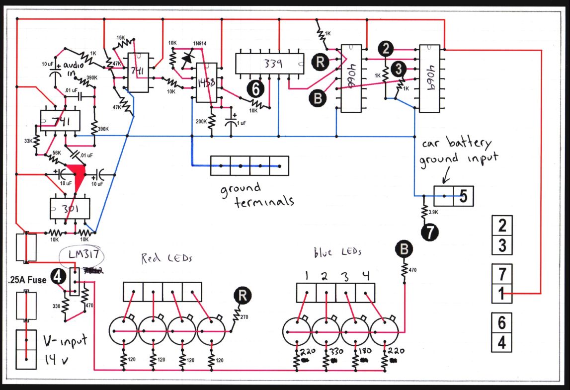
741 op-amp - compensated
LM301 op-amp - general purpose
1458 dual op-amp - compensated
LM339 quad comparator
4066 quad CMOS bilateral switch
4069 hex CMOS inverter
LM317 adjustable voltage regulator
2N2222A npn transistor
Final Assembly: refer to senior project.
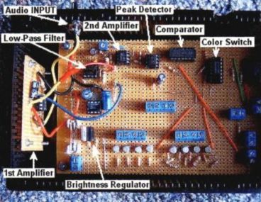
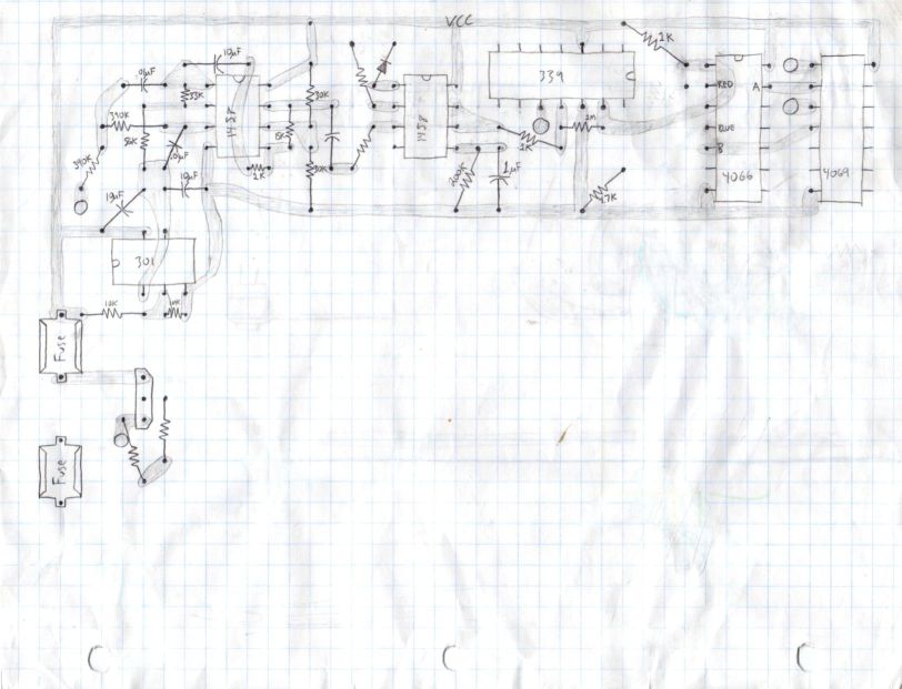
 <- final PCB layout (computer sketch)
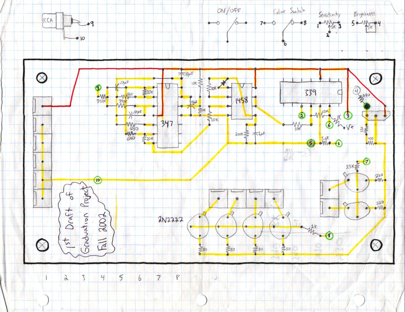
 <- final PCB layout (pencil sketch)
Schematics: 11 figures from senior project.
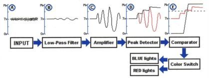
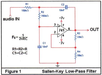 Sallen-Key
100Hz Low-Pass Filter
Sallen-Key
100Hz Low-Pass Filter
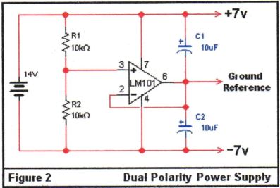 Buffer
/ Virtual Ground Generator: provides ½(+VS)
supply ground reference (+6V) for audio processing circuitry
Buffer
/ Virtual Ground Generator: provides ½(+VS)
supply ground reference (+6V) for audio processing circuitry
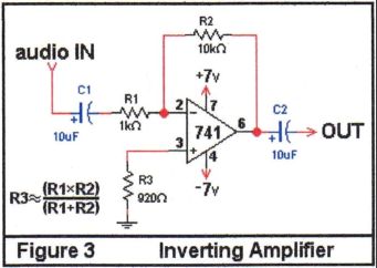 Inverting
AC Amplifier
Inverting
AC Amplifier
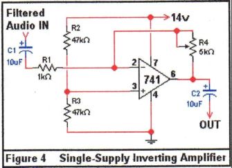 Noninverting
AC Amplifier
Noninverting
AC Amplifier
 Audio
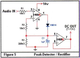
Amplitude (Peak) Detector: outputs peak value of AC signal as DC
voltage (6V to +12V)
Audio
Amplitude (Peak) Detector: outputs peak value of AC signal as DC
voltage (6V to +12V)
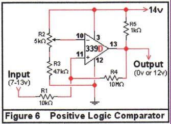 Voltage
Comparator: triggers LEDs when audio amplitude is above the DC
reference provided by trigger sensitivity potentiometer
Voltage
Comparator: triggers LEDs when audio amplitude is above the DC
reference provided by trigger sensitivity potentiometer
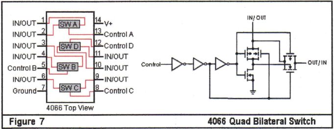 4066
Quad CMOS Bilateral Switch: internal device schematic
4066
Quad CMOS Bilateral Switch: internal device schematic
![]() Color
Switch: uses remotely controlled 4066 to interrupt on-board LED trigger
signals from a remote dash-mounted
Color
Switch: uses remotely controlled 4066 to interrupt on-board LED trigger
signals from a remote dash-mounted
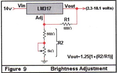 Adjustable
Voltage Regulator: LED Brightness Control
Adjustable
Voltage Regulator: LED Brightness Control
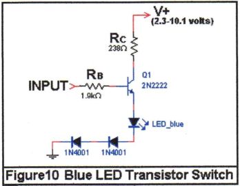 Blue
LED Transistor Switch
Blue
LED Transistor Switch
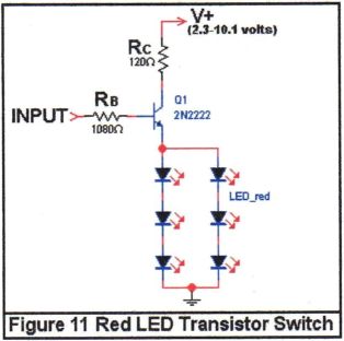 Red
LED Transistor Switch
Red
LED Transistor Switch
Other Schematics & Layouts:
 •
PCB layout of earlier version of circuit.
•
PCB layout of earlier version of circuit.
It was unsuccessful because I could not get the JFET input op-amps in the LF347 to generate the 6V ground reference function.
• I foolishly assumed that what worked for one op-amp would also work for another op-amp. This is when I learned a valuable lesson:
ALWAYS breadboard circuits before you build
them!!! Otherwise, you might build a circuit that doesn't work.
 •
one of many PCB layout brainstorms.
•
one of many PCB layout brainstorms.
• all layouts were designed by hand.
 •
another one of my many PCB layout brainstorms.
•
another one of my many PCB layout brainstorms.
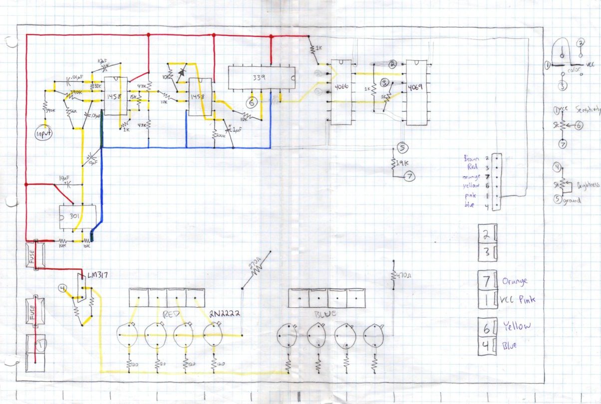
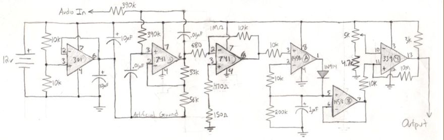 •
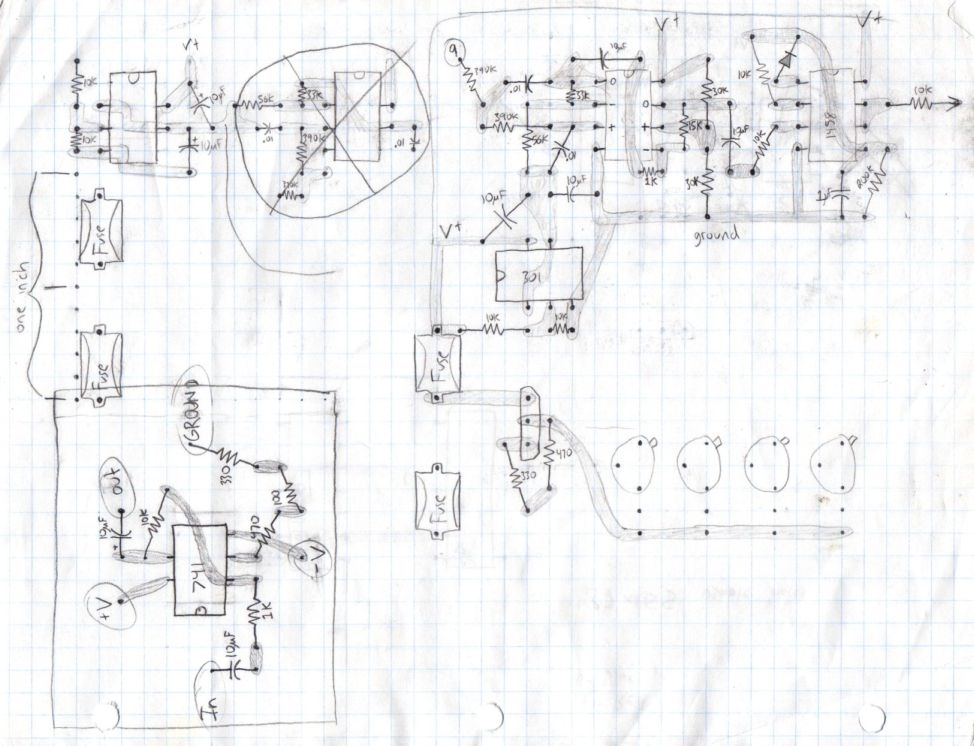
an early schematic of the audio processing circuitry
•
an early schematic of the audio processing circuitry
Improvements: refer to senior project.
• During my Junior and Senior years in High School, my knowledge of fundamental electronic theory was expanding so rapidly that each time when I'd finally finish constructing a project, there were already a dozen ways I could think of to improve it.
• This circuit functioned exactly the way I designed it, and seemed quite advanced at the time, but its electronic design needs much improvement and its overall functionality could be easily expanded to give the operator more options to maximize the experience. For this reason, I designed a much better Bass-Activated LED circuit.
• See my improved Bass-Activated LED Circuit [v2.0]
Back to my EE Page
Open my
Home page
© 2007, Devin R Ott