My Electrical Engineering:
LAST UPDATED: August 2014
![]()
Scroll down to see more!!!
Devins EE page: Return
to Top
[experience] [skills] [relevant courses] [independent study] [my EE childhood] [links] [books]
Electrical Engineering Experience:
My Personal Circuit Designs, Custom Applications,
Projects, Research, Reports,
and more!
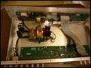
Aug 2013 ±15V Power Supply for my 8x8 RGBHV Matrix Switcher (my Home A/V System)
This is a
very standard circuit I designed, tested, assembled, and installed in a single
weekend to restore operation to the 8x8 composite video matrix switcher I
integrated into my centralized apartment A/V system. This unit handles all HD Video switching to
the (4) LCD/LED flat panel displays around my apartment.
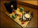
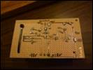
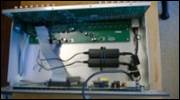

Aug 2013 ±15V Power Supply for my 8x8 Composite Video Matrix Switcher (my Home A/V system)
This is a very standard
circuit I designed, tested, assembled, and installed in a single weekend to refurbish
an 8x8 composite video matrix switcher I would later integrate into my
centralized apartment A/V system. This
unit now handles video switching for all DVD players/recorders, security camera
feeds, low-res cable tuner feeds (for SD recording), and play station in my
apartment.


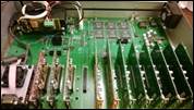
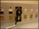
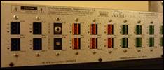
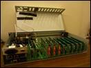
Dec 2012 Externally-Controllable +24V Power Supply for my BIAMP AudiaFLEX (my Home A/V System)
Well aware of my strong
background in circuit design / hardware design, my boss at Hoppmann Audio Visual
gave me a top-of-the-line BIAMP AudiaFLEX digital audio processor that wasnt
working. I was not surprised when I
opened the chassis to find a failed universal power supply.
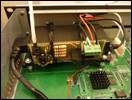
I custom-fitted a 24V@3A
external power supply inside the AudiaFLEX, along
with this custom control circuit, enabling third-party power on/off switching
via 3.5mm input port on rear panel.
Power
on/off is controllable via CMOS/TTL digital logic, or contact closure (input
mode is selectable via DIP switch).
When
nothing is plugged into the control port, the system operates in ALWAYS ON
mode and sends power through to the motherboard.
When a control cable is
plugged into the 3.5mm jack, the circuit enters EXTERNAL CONTROL mode wherein
the system default is POWER OFF,
unless a high
logic level or contact closure is sensed on the control input pins.
A
single bi-color LED [on rear panel] indicates power status: GREEN=ON; RED=OFF.

Oct 2011 Logic-Controlled Relay
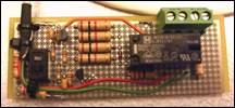
A simple transistor
switching/relay circuit I designed, tested, & assembled [in 4 hours of
personal time] to satisfy a contract deliverable in a touch-panel-controlled audio
system I programmed for my company. It
allows the digital logic output from a BSS Audio processor to trigger on/off
the powered speakers hanging from the auditorium ceilings.


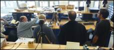
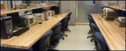
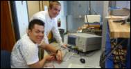
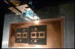
April 2011 Microwave Engineering Lab (August 2009 April 2011)
Employed by Penn State University as:
Laboratory Developer, EE 432 (August 2009 August 2010, Spring 2011)
Renovated the Microwave
Engineering Laboratory.
Modernized and expanded the
EE432 laboratory curriculum.
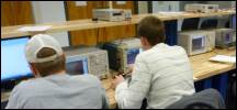
Trained students to operate
lab equipment (Network Analyzers, Spectrum Analyzers, etc.).




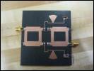
Teaching Assistant, EE 432 (Spring 2010)
Provided ALL laboratory
instruction for the senior/grad-level course, EE 432.
Authored course lab
activities (15% of course grade).
Guided students through the
design, fabrication, and testing of a 2.4GHz, +15dB balanced power amplifier
(25% of course grade).
Assisted students in the
use of Agilents Advanced Design System (ADS) software for RF circuit
simulation and PCB layout simulation.
Developed an ADS
2009 software tutorial.
Dec 2009
Class D Amplifier Solutions &
Practical Considerations
(Research)
This page summarizes my
research into switching amplifier design techniques and their implementation in
various consumer applications.
Research
topics include: Class D history; Topologies;
Modulation techniques; Filterless output topologies; Output switching circuits; Sources of distortion; EMI & noise considerations; Thermal considerations; PCB layout considerations; Power supply considerations.
Aug 2009
Amplifier Design Project, PSU AES (Audio
Engineering Society)
(September
2007 August 2009)
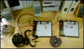
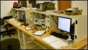
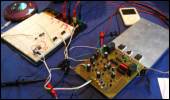
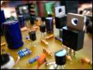
I led a team of
students in the design & construction of a high-fidelity audio power amplifier.
I Founded & Launched the 2-Year Design Project in September 2007; Sponsored By PSU AES ; Additional Funding From PSU EE Dept .
Designed and
prototyped preamp circuits, filters, power supplies, discrete transistor
amps, audio switching circuits, protection circuitry, sensor circuits.
Designed,
fabricated, and assembled the complete 50-watt
power amplifier and printed circuit
board.
Designed embedded microcontroller system;
developed source code in PICBASIC
PRO.
Documentation
for this project is organized in the following sections:
50-Watt Power Amp
(Dec 2008)
Headphones Amp (April 2008)
Preamplifier Circuitry (Jan 2009)
Power Supply (April 2008)
Embedded PIC
Microcontroller (Aug 2009)
PICBASIC
PRO Source Code (Aug 2009)


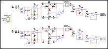






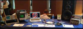
May 2009
High-Efficiency Headphones Amplifier
WINNER of the 2009 EE 410 Amplifier Design Competition for:
Highest Energy Efficiency (+10pts
extra credit)
Lowest THD (+5pts
extra credit)
I
led my team of 4 students to win this competition against 8 other teams in the
class. The assignment was to design a battery-powered headphones amp circuit
to meet the minimum project
specifications, and the competition
was to see which team could go the extra mile to improve on these
specifications the most. Our Professor, Mark
Warton, praised my team for being the only team in the class to satisfy the
minimum specifications, let alone improve on them. He also commended us on the quality of our
written report.


Mar 2009 Interviewed by a First-Year Engineering Student (for credit in his Freshman Seminar class)
I didnt know this
underclassman but I expect one of the EE professors I had worked with gave him
my contact info knowing I would be an indulgent interviewee. Im not sure if he was supposed to interview
me in person, but due to my very busy schedule, I had him send me the questions
and I responded in writing. I selfishly
over-indulged; going into deep description of what motivated me as a child and
adult to pursue electrical engineering.
All-in-all, this piece of writing provides a unique perspective into
my passion as an engineer.
Jan 2009 Letter of Support for Professor Mark Wharton (by PSU AES)
Professor Ken
Jenkins, the Department Head of Penn State Electrical Engineering , personally invited me to
write a letter of support for Professor Mark
Wharton, an exceptional Electrical Engineer and circuit-design mentor who
received nomination for an award recognizing his excellence as an
instructor. It was truly my pleasure to
have had this opportunity to express my appreciation for his significant
contribution to my development as an engineer & circuit designer.
Mar 2008 Power Amplifier Output Stage: BJT vs. FET (Research)
Written for ENGL 202
(Technical Writing), my comprehensive
research on the subject quickly overwhelmed the strict 3-page limit of the
writing assignment. To stay within the
page limit, I could only include ≈20% of the topics I researched. As an appendix, pages 5 and 6 are my
hand-written outlines for BJT research points and FET research points,
respectively.
Feb 2008 2-Way Loudspeaker PVC Towers (by PSU AES)
Documents the construction
of a 2-way loudspeaker using a dome tweeter and 6.5 woofer mounted in an elbow
section of large PVC piping.
This loudspeaker system was designed in 2002 by John Heake
of the Penn State Audio Engineering Society (PSU AES).


Jan 2007
Voltage Controlled Low-Pass Filter
This was a small piece of
an application I intended to design that would have united all of my current
automotive circuits (Bass-Activated LEDs & Engine-Controlled Neon Lights) under a single control
structure with even more functions and a better design. I halted my work on this project in September
2007 when I joined Penn States Audio Engineering Society (PSU AES) and
launched the two-year Amplifier Design Project.


May 2006
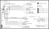
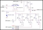
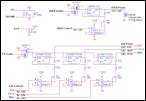
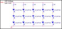
High-Power Outdoor Tent Light
Features a
fully-adjustable high-intensity tricolor LED array and 6V halogen bulb. The light fixture secures tightly to the
inside roof of the tent. In LED-mode, the brightness of each LED
array (red, green, and blue) is fully-adjustable so that the user may create
virtually any color desired. In Bulb-mode,
the halogen incandescent bulb can be adjusted from very bright to dim. The entire Tent Light application is
controlled by a small, low-power wired remote.
Requires 12Vdc @ 1A max.


May 2006 +9V 1.5A DC Power Supply
Designed to power a SONY
stereo boombox from an external 11V to 40V
unregulated DC source.


Mar 2006
Automotive Neon Lights: Dash-Mounted Control Circuit
This control panel houses
the main power & function switching for my engine-controlled neon power
circuit. It also contains circuitry that
integrates the bass-activated function of my LED circuits, plus additional
features.


Sept 2005
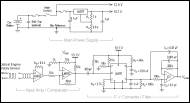
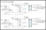
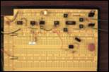
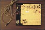
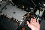
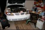
Automotive Neon Lights: Engine-Controlled Power Circuit
Converts the 100mV
square-wave of my engine's optical rotary sensor to a high-power DC supply
voltage that increases proportionally with the rate of engine rotation. The neon tubes are
powered by the DC supply so that when my engine is idle, the neons are off, but as my engine RPM increases, the neons turn on & become increasingly bright.
Dec 2004 Designing Systems for EMC (Research)
This is a topic I
researched for my own enjoyment while I was designing circuits for SPIRIT 3, a
corporate/university-sponsored project to develop an experiments payload for an
atmospheric rocket. NOTE: This is an
incomplete paper without citations, but I hope it will serve as a useful
reference to some.
Topics
include:
Methods of EMI Transmission (impedance coupling, electric & magnetic field
coupling, and far field coupling); Areas That Affect EMC (Distance
between source & victim, effective loop area, conductor quality, power
distribution quality, and shielding).
Oct 2004 EE 210 - Design Project
This course-mandated circuit & PCB design project
converts an 8-bit parallel input address to a 0-5V analog voltage, then uses a
simple 4-LED circuit to display the voltage level.


Oct 2004 Current-to-Voltage Converter
A simple amplifier circuit that varies the output
voltage range of an NT-5 magneto-resistive current sensor from F. W. Bell.

Aug 2004
Voltage Regulator Experiment (Research)
Tests the ability of an
op-amp to supply the reference potential for a high-power [fixed] voltage
regulator in order to control the regulator's output potential above ground.


Aug 2004
Up/Down Auto-Reverse 4-bit Binary
Counter
This circuit is designed to generate a back-and-forth
lighting effect using a 16-LED array fixture.

July 2004
Sound Amplitude Sensor
This circuit measures sound through a microphone and
converts it to a DC voltage proportional to the audio wave amplitude.


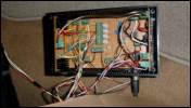
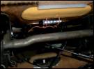
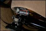
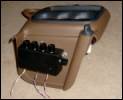
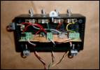
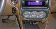
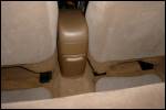
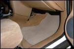
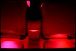
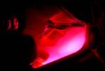
Aug 2003 Bass-Activated LED Circuit: verson 2
The improved version of my High School
graduation project : better circuits, more functions, more colors, and a
lot more LEDs.
Four types of high-intensity LEDs: Red, Green, Blue,
& Amber.
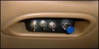
Two sensitivity adjustment
knobs:
o COARSE Sensitivity Adjustment: varies the DC reference voltage of the
comparator.
o FINE Sensitivity Adjustment: varies the gain of the second amplifier stage
that feeds into the peak detector circuit.
A switch lets me disable
the LEDs facing the rear seats, and another switch lets me disable the LEDs
facing my subwoofer box & amp in the trunk.








Feb 2003
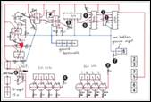
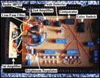
Bass-Activated LED Circuit: version 1
My High School Graduation Project for State College Area High School.
Red and blue high-intensity LEDs were mounted throughout my vehicle and
controlled by this circuit. The LEDs are
triggered by a comparator circuit that turns them on when the audio bass
(<100Hz) amplitude exceeds a reference voltage. I adjust the sensitivity of this circuit by
adjusting the comparator reference voltage via potentiometer mounted in the
side control panel of my vehicle. The
LED brightness is also adjustable from the control panel, and there is a switch
to select either blue LEDs only, red LEDs only, or
both the blue and the red LEDs.

Nov 2002
+12V Fixed DC Power Supply
Designed & constructed to power two 12V computer
fans from a standard 120Vac source. The fans were installed in my
friend's basement to encourage airflow through a ventilation shaft near a
wood-burning stove.
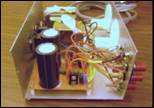
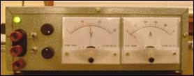
Dec 2001 ±30V 1.5A Variable DC Power
Supply
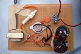
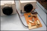
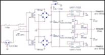
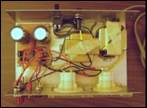
Dual-polarity adjustable bench-top voltage source for my
prototyping work. Two
voltage ranges: ±1.2V
to ±15V,
±15
to ±30V.
Devins EE page: Return
to Top
[experience] [skills] [relevant courses] [independent study] [my EE childhood] [links] [books]
My Skills:
Last updated: February 2011
Test
Equipment:
RF/Microwave: Network Analyzers, Spectrum Analyzers, Power Meters,
Noise Figure Meters, etc.
General Purpose: Power Supplies, Oscilloscopes, Function/Signal
Generators, Multimeters, Signal Analyzers, Frequency Counters, Logic Analyzers,
etc.
Software:
Circuit Design & Layout:
Agilents Advanced Design System (see
my ADS
2009 software tutorial)
AWR Microwave Office
National Instruments Multisim &
Ultiboard
OrCAD
SolidWorks
Logicworks
Computational & Programming:
MATLAB
LabVIEW
Microsoft Visual Studio
Other:
LaTeX
Microsoft Office (Excell, Word,
Powerpoint, Project, etc.).
Programming
Languages:
C/C++
PIC BASIC Pro
Microcontroller Assembly Language
TeX
HTML
Electronic Design:
Analog Circuits
linear & switching power
supplies, DC-DC Converters, thermal analysis & management.
power semiconductors (BJT, MOSFET,
IGBT), transistor switching circuits, driving reactive loads &
electromagnetic loads.
power amplifiers, discrete transistor
amplifiers, feedback theory (Control Systems), stabililty analysis, frequency
compensation.
op-amp circuits, passive & active
filters, timer circuits.
electronic components, device
parasitics and non-idealities.
RF design, distributed components
(i.e. microstrip), microwave couplers, filters, power amplifiers, matching
networks, etc.
electromagnetics, transducers,
transformers, stepper-motors, relays.
optical components, LEDs, photo
transistors, photo resistors, etc.
Digital Circuits
discrete logic, programmable logic
devices, ADCs, DACs, etc.
microcontroller programming &
supporting circuitry design.
Designing Circuits & Systems for EMC (Electromagnetic Compatibility)
PCB design, mechanical design, wiring
schemes, proper grounding schemes, shielding.
power distribution, effective pick-up
loop area, power & ground planes / ground filling, signal separation,
multi-layer PCB design, etc.
noise analysis (noise power, noise
figure, etc.), distortion analysis, spectral analysis.
Circuit Fabrication
PCB etching, PCB milling/routing (e.g.
using a Quick Circuit machine), prototype re-working, etc.
precision assembly, soldering SMD/SMT
and thru-hole packages, interconnects, wiring, etc.
component selection, parts searches,
cross-referencing obsolete parts, etc.
**UNDER
CONSTRUCTION**
Last updated: February 2011
Devins EE page: Return
to Top
[experience] [skills] [relevant courses] [independent study] [my EE childhood] [links] [books]
Relevant Courses:
*Completed for my
B.S.E.E. degree (Dec 2009) at Penn State University
Courses related to Circuit Design & Analysis:
EE 432 UHF and
Microwave Engineering (3 credits)
Transmission line and wave guide characteristics and
components; design UHF-microwave amplifiers, oscillators, and filters;
measurement techniques; design projects.
My PSU job(s) involving this course:
>> visit my Lab to learn more.
Laboratory Developer, EE 432
(8/2009 - 8/2010, Spring 2011)
Renovated Penn
States Microwave Engineering Laboratory.
Modernized and
expanded the EE 432 laboratory curriculum.
Trained
students to operate lab equipment (Network Analyzers, Spectrum Analyzers,
etc.).
Teaching
Assistant, EE 432 (Spring 2010)
Provided ALL laboratory
instruction for the senior/grad-level course, EE 432.
Authored course lab
activities (15% of course grade).
Guided students through the
design, fabrication, and testing of a 2.4GHz, +15dB balanced power amplifier
(25% of course grade).
Assisted students in the
use of Agilents Advanced Design System (ADS) software for RF circuit
simulation and PCB layout simulation.
Developed an ADS
2009 software tutorial.
EE 410 Linear
Electronic Design (3 credits)
Linear circuit design via integrated circuit processes.
Analog/digital converters, switched capacitor filters, phase lock loops,
multipliers, and voltage-controlled oscillators.
I led my team of four students to WIN
the EE 410 Amplifier
Design Competition [against 8 other teams] by designing
a battery-powered Headphones Amp with the highest energy
efficiency in
the class (+10pts extra credit), and the lowest THD
levels in
the class (+5pts
extra credit).
EE 311 Electronic
Circuit Design II (3 credits)
Electronic circuit design with consideration to single and
multi-device subcircuits, frequency response
characteristics, feedback, stability, efficiency, and IC techniques.
EE 310 Electronic
Circuit Design I (4 credits)
Properties of fundamental electronic devices, analysis of
DC, AC small-signal and nonlinear behavior, analog and digital circuit design
applications.
My PSU job(s) related to this course:
Laboratory
Assistant, EE 310 (Spring 2009)
Assisted students with
their EE 310 laboratory exercises and homework assignments.
EE 413 Power Electronics (3 credits)
Switch-mode electrical power converters. Electrical characteristics and thermal
limits of semiconductor switches.
EE 350 Continuous-Time
Linear Systems (4 credits)
Introduction to continuous-time linear system theory:
differential equation models, sinusoidal steady-state analysis, convolution,
Laplace transform and Fourier analysis.
EE 380 Linear
Control Systems (3 credits)
State variables; time-domain and frequency-domain design and
analysis; design of feedback control systems; root locus.
EE 403W Senior
Project Design (3 credits)
Project designs of analog and digital systems, interfacing, and
relevant electronic circuits, with an emphasis on technical communication
skills.
My EE 403W
Senior Project was to finishing designing the 50-Watt audio power
amp circuitry for the PSU AES Amplifier Design Project, and to design the
PCB Layout for good EMC (electromagnetic compatibility) to keep output THD very
low.
EE 210 Circuits
& Devices (4 credits)
Introduction to electrical circuit analysis, electronic
devices, amplifiers, and time-domain transient analysis.
My PSU job(s) related to this course:
Laboratory
Assistant, EE 210 (Fall 2008)
Assisted students with
their EE 210 laboratory exercises and homework assignments.
Courses related to Embedded Systems Design:
EE 316 Introduction
to Embedded Microcontrollers
(3 credits)
Introduction to microcontrollers in electronic and
electromechanical systems. Hardware and
software design for user/system interfaces, data acquisition, and control.
Developed
source code using assembly language, C++, and PIC BASIC Pro.
CMPSC201 Programming
for Engineers with C++
(3 credits)
Development and implementation of algorithms in a
procedure-oriented language, with emphasis on numerical methods for engineering
problems.
EE 362 Communication
Networks (3 credits)
Data transmission, encoding, link control techniques;
communication network architecture, design; computer communication system
architecture, protocols.
CSE 275 Digital
Design Laboratory (1 credits)
Introduction to digital design techniques.
CSE 271 Introduction
to Digital Systems (3 credits)
Introduction to logic design and digital systems. Boolean algebra, and introduction
to combinatorial and sequential circuit design and analysis.
Additional courses of interest:
ENGR497E Project
Management for Professionals
(3 credits)
This practical course covers the essential concepts and
skills needed to make effective contributions and have an impact on the
successful accomplishments of projects.
I completed
this course on my own initiative to maximize my effectiveness as a team leader
and project manager. This course did NOT
count toward my B.S.E.E. degree requirements.
ENGL202C Technical Writing (3 credits)
Technical Writing, serves students who are preparing for
careers in the sciences and applied sciences (particularly engineering).
Devins EE page: Return
to Top
[experience] [skills] [relevant courses] [independent study] [my EE childhood] [links] [books]
Independent
Study EE 496
EE496 COURSE DESCRIPTION: Creative projects, including research and
design, which are supervised on an individual basis and which fall outside the
scope of formal courses.
- With the approval of EE faculty members, I earned
these Independent Study credits for my extracurricular Research & Design
work.
EE 496 Independent
Studies (3 credits)
Dr. Julio Urbina Fall 2009
■ Researched class
D switching amplifier design techniques and its implementation in
consumer applications.
■ Topics emphasized:
Class D history
Class D topologies & modulation techniques
EMC: EMI, noise consideration
Output Filter vs. filterless topologies
Switching circuits (half-bridge vs. H-bridge)
Sources of distortion in class D amps
Thermal considerations
PCB layout considerations
Class D solutions for:
‒
Mobile applications
‒
High power
applications
‒
High fidelity
applications
EE 496 Independent
Studies (3 credits)
Dr. Julio Urbina Summer 2009
■ Designed the implementation
of a PIC microcontroller to manage the inner-processes & user
interface of the PSU AES Amp Project (the
complete application).
■ Some of these features
include:
Monitoring & controlling internal operations of the complete
application (e.g. startup/shutdown power sequences, detecting & responding
to fault conditions, etc.)
20x2-character LCD to display [among other things]:
‒
Date & time.
‒
Input source
selection (1 of 3 stereo input sources), volume MUTE and volume ATTENUATE.
‒
Peak output
voltage, current, and average power of left & right amplifier channels.
‒
Temperature (°F and
°C) of heatsinks & ambient temperature inside
chassis.
‒
Fault conditions
(e.g. DC offset detection, thermal warning, thermal shutdown, etc.).
‒
Output signal
clipping due to Over-Voltage (Vout > 26Vpeak) or
Over-Current (Iout > 3A,peak).
Sampling sensor voltages at analog inputs (for Vout,
Iout, Temp) and converting
to proper numeric data for the LCD.
Controlling the amplifiers power relays and signal relays.
Receiving & interpreting commands from the front-panel user
interface.
EE 496 Independent
Studies (2 credits)
Dr. Julio Urbina Fall 2008
■ Designed & prototyped
the following circuits for the PSU AES Amp Project:
Preamplifier [input] stages:
‒
Three-input stereo
switching circuit (for 3 stereo input sources)
‒
Bass/treble tone
control circuit
‒
Volume &
left/right balance circuit
Sensor circuits to monitor power amplifier:
*These circuits sense a physical or electrical parameter and output a
proportional 0V to +5V DC voltage to be monitored by the analog inputs of a
microcontroller.
‒
Output voltage
amplitude sensor
‒
Output current
amplitude sensor
‒
Temperature of
power amp heatsinks
EE 496 Independent
Studies (2 credits)
Mr. Timothy Wheeler Summer 2004
■ Designed & prototyped
analog circuits, digital circuits, and investigated the effectiveness of fixed
voltage regulators employed in a specific configuration. See the following reports for more info:
Sound
Amplitude Sensor: This circuit
measures sound from a microphone and converts it to a DC voltage proportional to
the audio wave amplitude. Low-THD headphones amp
UP/DOWN Auto-Reverse 4-bit Binary
Counter: designed to generate a
back-and-forth lighting effect using a 16-LED bar fixture.
Voltage Regulator Experiment: Tests the ability of an op-amp to supply the reference potential for a high-power [fixed] voltage regulator in order to control the regulator's output potential above ground.
Devins EE page: Return
to Top
[experience] [skills] [relevant courses] [independent study] [my EE childhood] [links] [books]
My EE Childhood: I was born
to be an Electrical Engineer!
*written June 2006
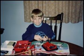 Here I am (left), a few months before my 9th
birthday (spring 1994), in the process of removing a motorized propeller
circuit from a TYCO hovercraft and
preparing to mount it to one of my extravagant LEGO Technic creations.
I was in my EE infancy back then; an adventurous young boy just beginning to realize the AWESOME power of electronic technology. I had already spent years disassembling equipment and marveling at circuit boards, but I was finally developing a qualitative understanding of current and voltage, while taking full advantage of my familys 1989 World Book encyclopedia volumes.
I was fascinated by electromagnetic phenomena. I experimented with numerous home-wound electromagnets, and even constructed a single-pole DC pulse motor for extra credit in 4th grade (fall 1994) *special thanks to my elementary school teacher, Mrs. Karen Boston*. I would later construct the same DC pulse motor during a Physics lab activity as a high school Senior (Spring 2003).
Driven by an intense passion for
electronic invention, I continued experimenting by creating simple security
alarms, small motorized machines, and a variety of electronic ignition systems
for homemade fireworks. I also developed
a passion for audio, and as an enthusiastic 10-year-old I began operating the
professional sound equipment (mixers, power amps, etc.) during Sunday services
at my local church, The State College Free Methodist Church.
While serving as my churchs Sound Man from ages 10 to 12, I
continued with my own research and electronic design/customization. My interests expanded to include subwoofer
& mid-range speaker box design, and more notably into the area of wireless
electronics with a botched attempt at making a wireless remote ignition system
for my ESTES model rockets.
With the advent of my inquiries into wireless technology, it became clear that my elaborate engineering ideas had begun to exceed my limited abilities as a novice. I wanted desperately to keep learning but simply didnt know how. My parents lacked the necessary scientific background to offer me any meaningful direction, so most of my more advanced ideas unfortunately never materialized. Nonetheless, it seems I was gifted with an all-consuming passion for electronic invention; a passion that would then lay dormant until a great high school teacher, Mr. Douglas Ripka, gave me the knowledge & direction I needed to rekindle my fiery zeal and start learning and experimenting again on my own.
After completing my first Electronics course at age 15, Id obtained enough background knowledge to begin independently studying EE textbooks. With the help of Mr. Ripka in the years that followed, I gained impressive skill & extensive experience in all aspects of electronic circuit design, and have continued to this day on my lifelong journey of electrical engineering.
Devins EE page: Return
to Top
[experience] [skills] [relevant courses] [independent study] [my EE childhood] [links] [books]
Some EE Links:
IEEE: Institute of Electrical and Electronics Engineers - www.ieee.org
AES: Audio Engineering Society - www.aes.org/
PSU AES: Pennsylvania State University student section of AES - www.clubs.psu.edu/up/aes
GlobalSpec: The Engineering Search Engine - www.globalspec.com
Device Manufacturers:
Analog Devices - www.analog.com
Linear Technology - www.linear.com
National Semiconductor - www.national.com
Fairchild Semiconductor - www.fairchildsemi.com
Texas Instruments - www.ti.com
STMicroelectronics - www.st.com
Mini-Circuits - www.minicircuits.com
LC-LED - www.lc-led.com
Retail Suppliers:
Allied Electronics - www.alliedelec.com
Digi-Key - www.digikey.com
Newark - www.newark.com
Mouser Electronics - www.mouser.com
Jameco Electronics - www.jameco.com
Electronix Express - www.elexp.com
Devins EE page: Return
to Top
[experience] [skills] [relevant courses] [independent study] [my EE childhood] [links] [books]
My EE books: Last updated January 2008
I began this list in 2006, but now the idea of listing my EE books
seems silly and unnecessary.
I will soon replace this list with a much shorter list of only my
favorite EE books.
The Art of Electronics;
2nd Ed
Paul Horowitz, Winfield Hill
1989, Cambridge University Press, - 1125 pages
Microelectronics:
Circuit Analysis and Design; 3rd Ed
Donald A. Neamen
2007, McGraw-Hill, - 1370 pages
Engineering Circuit Analysis;
6th Ed
W.H. Hayt, J.E. Kemmerly, S.M. Durbin
2002, McGraw-Hill, - 781 pages
Solid State Electronic
Devices; 6th Ed
Ben G. Streetman, Sanjay Kumar Banerjee
2006, Prentice Hall, - 581 pages
Signal Processing & Linear
Systems
B. P. Lathi
1998, Oxford University Press, - 850 pages
Electromagnetic Compatibility Handbook
Kenneth L. Kaiser
2004, CRC Press, - 2568 pages
Fundamentals of Applied
Electromagnetics; 5th Ed
Fawwaz T. Ulaby
2006, Pearson Prentice Hall, - 464 pages
Electronic Components and Measurements
Wedlock, Roberge
1969, Prentice Hall, - 338 pages
Basic Electronics Theory; 4th Ed
Delton T. Horn
1994, McGraw Hill, - 692 pages
Op Amp Applications Handbook,
a Volume in the Analog Devices Series
Walt Jung, and technical staff of Analog Devices Inc.
2005, Newnes, - 878 pages)
Op Amps, Electronic Circuit Guidebook;
Volume 3
Joseph J. Carr
1997, Prompt Publications, - 273 pages
Active Filter Cookbook;
2nd Ed
Don Lancaster
1996, Newnes, - 240 pages
The Audiophile's Project
Sourcebook
G. Randy Slone
2001, McGraw-Hill, - 361 pages
Timer, Op Amp & Optoelectronic Circuits &
Projects
Forrest M. Mims
2000, Master Publishing, - 128 pages
Power Supplies, Switching Regulators, Inverters, and
Converters;
2nd Ed
Irving M. Gottlieb
1994, McGraw-Hill, - 479 pages
Building Power Supplies; 2nd Ed
David Lines
1997, Master Publishing, - 124 pages
Automotive Computer Controlled Systems
Allan Bonnick
2001, Butterworth-Heinemann, - 252 pages
The Car Stereo Cookbook
Mark Rumreich
1998, McGraw-Hill, - 296 pages
Building Speaker Systems;
3rd Ed
McComb, Evans
1998, Master Publishing, - 178 pages
Music Technology, Essentials of
Mark Ballora
2003, Prentice-Hall, - 248 pages
The 2001 ARRL Handbook;
78th Ed
ARRL (American Radio Relay League) - the National
Association for Amateur Radio
2000, ARRL, - 1216 pages
The 1972 ARRL Handbook;
49th Ed
ARRL (American Radio Relay League)
1972, ARRL, - 1216 pages
Basic Communications Electronics
Jack Hudson, Jerry Luecke
1999, Master Publishing, - 220
pages
Upgrading and
Repairing PCs; 17th Ed
Scott Mueller
2006, Que Publishing, - 1582 pages
Programming & Customizing PICmicro
Microcontrollers; 2nd Ed
Myke
Predko
2002, McGraw-Hill, - 1190 pages
Essential C++:
For Engineers and Scientists; 2nd Ed
Jeri R. Hanly
2002, Addison Wesley, - 534 pages
Programming Microcontrollers in C;
2nd Ed
Ted Van Sickle
2003, Newnes, - 454 pages
Introduction to Logic Design;
2nd Ed
Alan B. Marcovitz
2005, McGraw-Hill, - 652 pages
Comprehensive Dictionary of Electrical Engineering;
2nd Ed
Phillip A. Laplante
2005, CRC Press, - 758 pages
Encyclopedia of Electronic Circuits;
Volume 7
Rudolf Graf, William Sheets
1999, McGraw-Hill, - 1128 pages
Encyclopedia of Electronic Circuits;
Volume 6
Rudolf Graf, William Sheets
1996, McGraw-Hill, - 789 pages
Telephone Electronics;
4th Ed
Bigelow, Carr, Winder
2001, Newnes, - 402 pages
Animatronics
Edwin Wise
2000, Prompt Publications, - 273 pages
Devins EE page: Return
to Top
[experience] [skills] [relevant courses] [independent study] [my EE childhood] [links] [books]
Return to my Home page
© 2014, Devin Robert Ott
