Up/Down Auto-Reverse 4-bit Binary Counter
Devin R Ott
Design - completed in August 2004
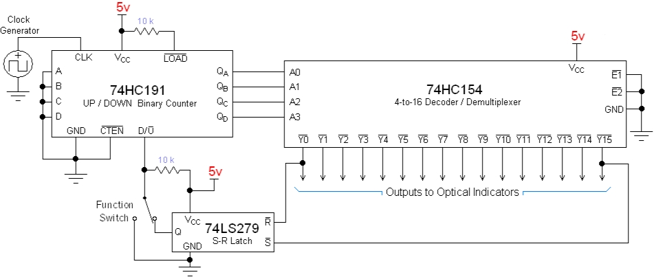
When power is first applied to the circuit, the binary
output of the ’191 counter is randomly generated by the four internal
flip-flops. The device will then begin counting with the rising edge of
the clock pulses, in a direction determined by the state of the D/U pin.
The 4-bit binary output of the ’191 counter is decoded by ’154 which triggers
the corresponding output to momentarily pulse low.
The count direction pin (D/U) is determined by the output of
the ’279 S-R latch. When the counter reaches the minimum value (0), the
’154 decoder triggers the corresponding output pin (Y0), causing the S-R latch
to reset the count direction to increment. When the counter reaches the
maximum value (15), the decoder’s (Y15) output is triggered, setting the count
direction back to decrement. This arrangement causes the ’191 to repetitively
reverse directions at its endpoints, counting infinitely back and forth along
its 4-bit (0-15) domain.
This type of electronic counting function is commonly used
to generate moving light displays. For example, the decoder’s sixteen
outputs could each be connected to one of sixteen corresponding light
indicators. Positioning these lights consecutively in a line would create
the effect of a spot of light moving back and forth along the line as the ’191
counted.
For an added capability, a SPDT (center off) switch can be
used to control the counting function. In the switch’s current position,
the D/U pin is controlled by the ’279 latch, so the counter is in the
“auto-reverse” mode. When the switch is in the center position, the 10kΩ
pull-up resistor brings the D/U pin up to a high logic value, setting the
counter to “decrement” mode. With the auto-reverse function disabled, the
counter will reach a maximum or minimum and start back from the other end,
always counting in the same direction. When the switch is pushed all the
way to the left, the D/U pin is grounded, causing the counting direction to
switch to “increment” mode.
The most common method of optical indication when dealing
with logic devices are LEDs (Light Emitting Diodes). Figure 2 illustrates
a very basic yet affective light indicator circuit. The ’154 decoder’s
outputs are normally in the high logic state and they pulse low when triggered
by the counter. So in normal operation, the voltage at the ’154 output
pin is around 4 volts, placing a potential across the LED that is of
insufficient magnitude to allow current to flow. When the output pin is
triggered, the LED’s cathode is pulsed to a low logic state, allowing the diode
to sink current into the decoder’s output, and momentarily light up.
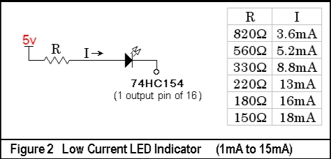
The ’154 outputs can sink an absolute maximum current of 25mA, so just to be
safe, it shouldn’t be used to sink more than 20mA. If a more powerful
light indicator is required, the circuit in Figure 3 can be used to switch high
intensity LEDs with load currents in excess of 100mA. This indicator puts
a lesser demand on the decoder’s outputs, consistently drawing a mere 1mA
source current into the transistor’s base when activated.
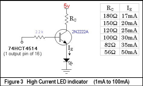
Unlike Figure 2, this is a positive logic LED indicator
triggered by a high logic pulse. To achieve the same “moving light”
function, this indicator would have to be used on a decoder with outputs that
are normally low. The ’4514 4-to-16 decoder can perform this
function. However, if the ’4514 is to be used in place of the ’154
decoder, a latch with positive logic S-R inputs would be required to maintain
the auto-reverse function.
Back to my EE Page
Back to Home
© 2006,
Devin R. Ott