Introduction: (written
9-4-06)
Designed
to monitor current consumption of various circuit board trays on an atmospheric
sounding-rocket payload for experimental study.
Support Module Current Sensors
Devin
R Ott
Design
- completed in October 2004
The
supply currents of each device will be measured by the NT-5 magneto-resistive
current sensors from F.W. Bell technologies. These current-to-voltage
converters have a nominal current rating of ±5 amps, and a corresponding
nominal output of ±2.5 volts. In other words, the currents sensors
output: VM=1/2IIN
Now that we have a voltage (VM) proportional
to the supply current, we can employ an op-amp to fit our desired voltage range
into the 0 to 5 volt window required for the PCM. For example, a 0-100mA
measurement range would create a 0-50mV output range, requiring an amplifier
gain of 100V/V before going to the PCM.
The circuit below was designed to represent
a current range (0 to IMAX) as a DC voltage range (0 to 5 volts)
depending upon the value of the feedback resistor R2.
To measure (0 to IMAX) set:
R2 =10,000÷IMAX
To calculate IIN from the final
output voltage (VOUT): IIN
= (VOUT÷5)×IMAX
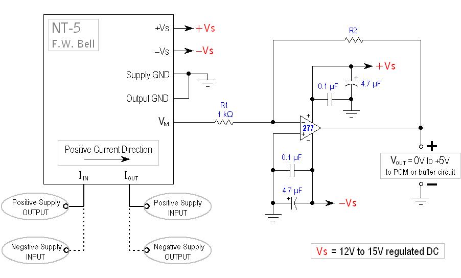
As you may have noticed, the measured currents of both
+ and – supplies will be opposing the Positive Current Direction specified
on the NT-5 sensor. In other words, the sensor will be measuring negative
current, and thus outputting a negative voltage. This was done to allow
the amp stage to be an inverting follower, the most stable type of op-amp
configuration.
Power Supply Bypassing:
The most crucial stabilizing components are the by-pass
capacitors in parallel with the supply voltages. When placed near the
op-amp, the capacitance provides extra filtering on the power-lines and decouples
noisy AC signals that can cause the amplifier circuits to oscillate.
A high value capacitor (1 µF to 10 µF) is used for low
frequency bypassing and is typically an aluminum or tantalum
electrolytic. Electrolytic capacitors become ineffective as frequency increases,
so a more stable capacitor (mylar, ceramic or mica) is used to decouple the
high-end noise.
These high-end bypass caps typically range from 0.01 µF
to 0.1 µF, and are most commonly ceramic due to their high availability and low
cost.
IMPORTANT:
the by-pass capacitors should be mounted as close to the op-amp as possible.
(no
farther than 6 inches).
Calculations:
IIN measured supply
current ( A )
IMAX the maximum desired measuring
current ( A )
VM output voltage from
NT-5 current sensor ( V )
VMAX the sensor’s output voltage (VM)
when measuring IMAX ( V )
AV the op-amp’s
voltage gain ( V/V )
VOUT final output voltage (0 to 5
volts DC) from op-amp ( V )
VM = 1/2IIN
AV = R2/R1
AV = VOUT÷VM
The required op-amp
gain: AV = 5÷VMAX AV
= 10÷IMAX
AV = R2/R1 = 10÷IMAX
Letting R1=1 kΩ: R2/1000
= 10÷IMAX
R2 = 10,000÷IMAX
The measured current: IIN = (VOUT÷5)
× IMAX
Back to my EE Page
Back to Home
© 2006,
Devin R. Ott