Introduction: (written
9-3-06)
This
circuit detects sound through a microphone and converts it to a DC voltage
proportional to the audio wave amplitude.
I
originally designed this sensor to measure my car engine's rotary speed (RPM)
by the volume of sound it produced - I wanted to avoid physical interfacing
with my engine's electronics, of which I knew little about at the time.
However, numerous conditions (that I won't bother mentioning) make this an undesirable
sensor for my automotive application, so I researched engine electronics and
found the perfect electrical parameter to interface with for a precision
RPM-to-voltage converter (Engine-Controlled
Power Circuit).
But
this sound amplitude detector can still lend it's service to applications used
in less extreme environmental conditions
Automotive Sound Level Sensor
Devin
R Ott
Design
- completed in August 2004
Click on schematic
for larger view
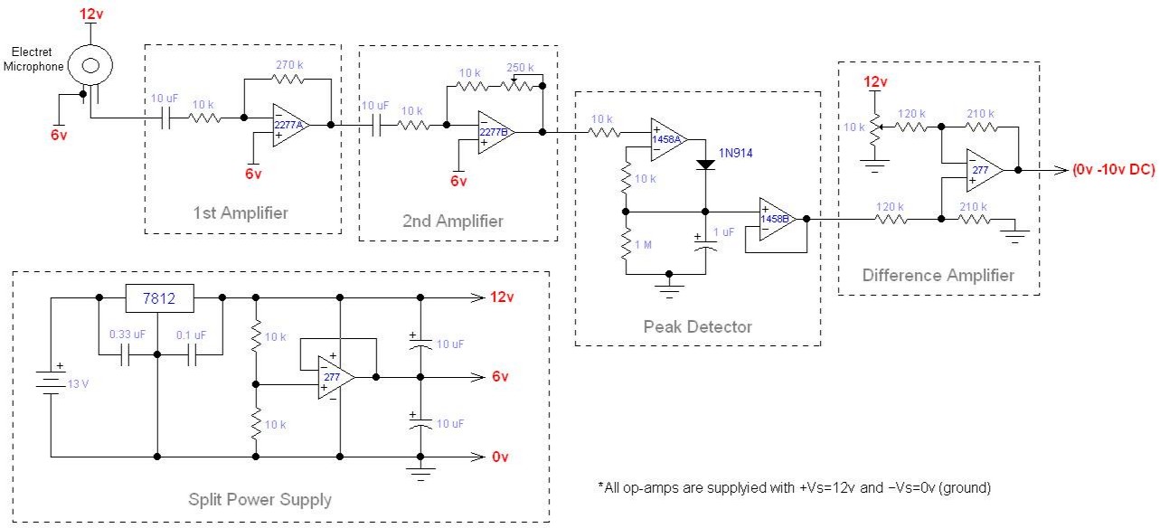
This circuit uses an electret microphone to
convert the audio engine noise to an electrical AC signal that fluctuates
above/below 6 volts. This signal is sent through two amplifier stages
built around the OPA2277 dual op-amp, providing an adjustable voltage gain from
27 to 675. The series RC inputs of these amplifiers create a low cut-off
frequency of 1.6 Hz, allowing them to block DC while amplifying audio frequencies.
The 2nd stage can be adjusted to output a maximum 6 volt amplitude
when the engine is loudest, creating a 0 to 6 volt AC amplitude that changes
proportionally with the engine noise.
The AC signal is then rectified and filtered
by the peak detector which smoothes out the positive peaks and represents the
signal as it’s 6 to 12 volt DC equivalent. In reality, the peak detector’s
1458 dual op-amp is not equipped with rail-to-rail outputs, so the real output
voltage range is from 6 volts to about 11.7 volts DC.
This voltage range is then sent to a difference
amplifier (OPA277 single op-amp) that subtracts about 6 volts from it, and
amplifies the result by a 1.75 voltage gain. The subtracted voltage reference
is programmed by a 10k pot, allowing one to account for the minimum engine
noise level.
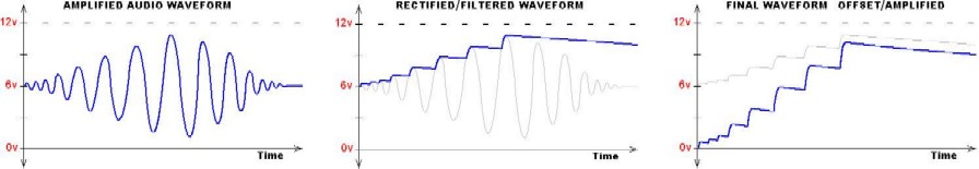
When the engine is off (no
noise) the output of the peak detector is 6 volts. However, when the
engine is running in the idle position (minimum noise) the peak detector is
outputting 6.5 volts. By adjusting the subtracted voltage to 6.5 (instead
of 6), the difference amplifier would output zero volts when the engine noise
was minimum (no throttle), and about 10 volts DC when the noise was maximum
(full throttle).
The entire circuit is
powered by the car battery voltage, which is immediately filtered and
stabilized by the 12 volt regulator. The AC amplifier stages of this
circuit require a dual polarity supply, so an OPA277 single op-amp has been
configured to regulate its output at ½ the supply voltage (6 volts DC). This
voltage acts as a ground reference, while the 12 volt and 0 volt potentials of
the regulator are supplying ±6 volts relative to that reference. So the
AC signals are fluctuating above and below 6 volts DC, relative to the ground
potential of the car battery.
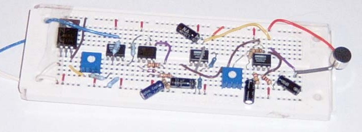
Prototype:
Back to my EE Page
Back to Home
© 2006,
Devin R. Ott